
![]()
 |
|
|
|
|
Intusoft
Newsletter Issue #54, November 1998
Copyright
©2002 Intusoft, All Rights Reserved
| In This Issue | |||
|
2 4 4
6 |
New ICAP/4 8.x.6 Adds RSS, EVA, Sensitivity and Worst Case Analyses Bonus Web Stuff: IBIS 2 SPICE Converter, Units Calculator & Models |
6 12
13 14 |
|
New ICAP/4 8.x.6 Adds RSS, EVA, Sensitivity and Worst Case Analyses
The new release of ICAP/4 8.x.6 includes several major feature additions. ICAP/4Windows (Figure 1) gets new RSS, EVA (Extreme Value), Worst Case, and Sensitivity analyses. In addition, the powerful Design Validation and automated measurements feature (Design Validator) has been added. ICAP/4Rx has added new mixed-signal simulation capabilities and digital models. The Design Validator product is now sold as ICAP/4 Professional and includes the automatic simulation and data presentation of all failure modes; a feature formerly limited to Test Designer. The update is summarized in Table 1.

|
|
|
ICAP/4 Professional (previously called Design Validator)
|
RSS, Extreme Value, Worst Case, and Sensitivity are now available for AC, DC, Transient and operating point analysis. Users can define their own “Simulation Template” scripts to perform complex analysis sequences like those used for RSS and EVA (See Figure 2).
Simulation Templates
and Automated Measurements
One of the unique new features in 8.x.6 is called “Simulation Templates”
(Figure 2). These templates are command scripts that direct the IsSpice4
simulator to perform complex analyses and manipulate the database of information
stored in the schematic. The initial release of Simulation Templates includes
scripts that perform worst case, RSS, sensitivity and EVA analysis for AC, DC
and Transient analysis as well as the traditional operating point analysis.

Simulation Templates change parameters one at a time, measure and record the resulting changes in circuit operation, and provide a summarized report consisting of user-defined measurements (Figure 2). The measurement scripts are setup using an easy-to-use Wizard approach. Extensive waveform measurements across all simulation domains are provided. Programming and script writing is not necessary. Once the measurements are setup, they happen automatically when a simulation is finished.
Expanding these traditional SPICE analyses using simulation templates requires single value measurements to be presented for perturbation (sensitivity) analysis. The capability offered by automatic measurement scripts is needed to make these easily applicable to analyses that produce vector data, such as a transient analysis. For example, we can speak of the sensitivity of the output’s rise time with respect to the change of a parameter value. The sensitivity of the entire output waveform would be possible to compute, but we couldn’t mathematically identify the best output waveform - while we could identify things like the smallest rise time or the greatest standard deviation. These scalar results are needed to make decisions about their relation to parameter values and to use that decision to find parameter values that correspond with a goal; for example, to make a best or worst case result.
|
***** RSS Analysis data for
V(10) COMPONENT PARAMETER NOMINAL TOLERANCE SENSITIVITY CONTRIBUTION r3 resistance 3.90e+002 2.00e-002 0.00e+000 0.00e+000 q1 bf 1.05e+002 3.50e-001 1.28e-026 4.48e-027 q1 is 1.52e-014 2.00e-001 3.26e+002 6.52e+001 r4 resistance 1.00e+003 2.00e-002 -7.76e-005 -1.55e-006 q2 bf 1.05e+002 3.50e-001 6.93e-004 2.43e-004 q2 is 1.52e-014 2.00e-001 9.26e+011 1.85e+011 r5 resistance 4.70e+002 2.00e-002 1.71e-005 3.41e-007 r6 resistance 8.20e+002 2.00e-002 1.71e-005 3.41e-007 q3 bf 1.05e+002 3.50e-001 6.55e-006 2.29e-006 q3 is 1.52e-014 2.00e-001 -8.83e+011 -1.77e+011 r7 resistance 4.70e+002 2.00e-002 2.96e-005 5.93e-007 r8 resistance 2.70e+001 2.00e-002 1.74e-003 3.48e-005 |
|
VECTOR OP-VALUE RSS-VALUE
TOLERANCE% HI-VALUE LO-VALUE V(10) 1.11e+000 2.58e-002 2.33e+000 1.13e+000 1.08e+000 |
The ability to measure key performance behavior and use the measured results within other analyses such as stress and sensitivity provides a powerful means to automate performance analysis and design optimization.
Tight integration of the Simulation Templates into the IsSpice4 mixed-signal simulator greatly increases processing speed because the simulator is not exited or reloaded, and netlists don’t need to be re-compiled. You can automatically run multiple simulations in either batch or interactive mode while varying toleranced parameters at each pass. The results are automatically extracted and displayed against user-defined limits. “Stress alarms” are automatically displayed when a performance parameter is out of tolerance.
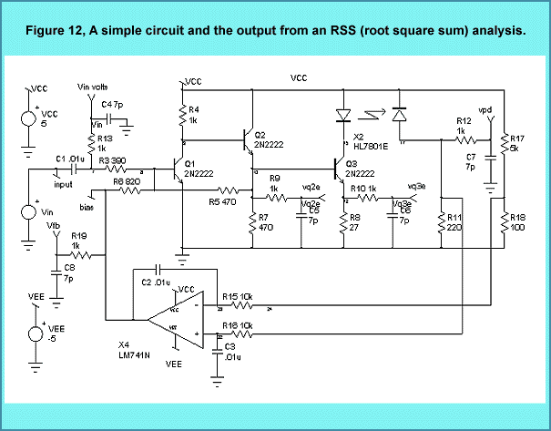
Figure 12 shows an example amplifier circuit and the basic output RSS data in tabular form. The data shows the individual contributions from each component and model parameter as well as the final RSS value at node 10. Output from the EVA, sensitivity, and worst case analyses is similar.
The Design Validator™ feature, which has been added to ICAP/4Windows, keeps track of multiple circuit configurations, analysis setups and test measurements. It then runs an entire suite of tests automatically and creates a report that summarizes the measurements and pass-fail grades (Figure 2). This powerful capability extends SPICE well beyond its current single simulation oriented boundaries. The measurements can be made on any number of nodes, currents or devices. This is all done without the need for any user interaction.
The feature additions in particular, the design validation and Simulation Templates, put ICAP/4Windows in a class by itself. No other SPICE tool has this feature set at any price. For more details on version 8.x.6, visit www.intusoft.com.
SPICE models for nonelectrical devices often use analogs of voltage and current to signify other quantities. To SPICE it’s all differential equations, but from the user’s viewpoint, different models may communicate in different sets of units. Bidirectional conversion conserves power/energy across its boundary. Electrical engineers encounter this most frequently in transformers and power converters. When we extend IsSpice4 to mechanical systems, the bidirectional process is also seen in motors and gears. Using bidirectional conversion to convert from one system of units to another, for example, converting rad/sec to RPM has the advantage of being able to initialize a system in a more familiar regime.
|
.Subckt rad2deg 1 2 ; Bidirectional
conversion Radians, Degrees * Nodes : 1 : input node (radians) 2 : output node (degrees) x1 11 0 2 0 xfmr {ratio=57.29577951} ; gain = 180/pi r1 2 0 1meg rin 1 11 1u .ends ***** .Subckt kwh2tons 1 2 ; Bidirectional conversion kw-hr, tons tnt * Nodes : 1 : input node 2 : output node x1 11 0 2 0 xfmr {ratio=845.505455u} rin 1 11 1u rout2 2 0 1meg .ends |
| Figure 3, Two examples of bidirectional unit converters. The ratio value controls the parameter relationship. |
The subcircuit in Figure 3 solves the unit conversion problem by using a transformer and a smooth transitioning source to “slowly” establish the initial condition. The cosine shaped transition (see Intusoft Newsletter #53) limits the acceleration and jerk (first and second derivatives).
Intusoft offers free software utilities and useful downloads on its web site (www.intusoft.com). A new Units Converter/Calculator and an IBIS-to-SPICE converter are now posted; other free items (SPICE evaluation versions, models, technical articles, wallpaper and application notes) are also on the site.
The Units Calculator is a novel program that converts between various types of quantities, i.e. distance (inch, foot yard, mile, meters), energy (erg, joule, ft-pound), force (dyne, newton, pound), and pressure (millibar, bar, pascal, mm Hg). It also evaluates sequences of mathematical expressions. It is programmable - users may add their own unit conversions and constants. The calculator supports trigonometric, transcendental, and many common math operations.
The IBIS-to-SPICE converter translates IBIS (I/O Buffer Information Specification) data sheet information into SPICE models and supports IBIS versions 1.1, 2.1, and 3.0. The converter can be used with ANY vendor’s SPICE program including IsSpice4, PSpice©; and Hspice©;.

The converter parses the IBIS data sheet and extracts the appropriate data tables, pin parasitics, package parasitics, and ramp time information and merges the data into a model template file, yielding a SPICE subcircuit. The default model template that is provided is for Intusoft’s IsSpice4 syntax; templates can easily be constructed for other simulators in order to accommodate differences in behavioral element syntax. Instructions are included in the on-line help file. The converter in Figure 4 generates models for the multiple pins and signals that may be included in a single IBIS data sheet, and can also extract typical, best, or worse case models.
The “Model Template” file describes the structure of the SPICE subcircuit that the converter will produce. The format is flexible, allowing you to produce syntax for virtually any simulator and for any subcircuit topology.
IBIS is a standard for electronic behavioral specification of integrated circuit input/output analog characteristics. It includes V/I data so as not to disclose any circuit/process information. It can be thought of as a behavioral modeling specification suitable for transmission line simulation of digital systems, and is applicable to most digital components. IBIS Version 1.0 was first introduced in June, 1993. While IBIS Version 2.1 remains the official standard, IBIS Version 3.0 containing some technical extensions was ratified on June 12, 1997 by the EIA/IBIS Open Forum. Work will continue on refining this version for eventual submission for national and international standardization consideration. Updates to the IBIS-to-SPICE converter will be posted as necessary.
Magnetics Designer is a versatile tool that designs all types of layer wound transformers and inductors. It is unique in the marketplace. The frequency range of the magnetics that can be designed extends from DC to over 5MHz. Unlike Finite Element Analysis (FEA) programs, Magnetics Designer is a synthesis tool as well as an analysis tool. With FEA based tools you must enter far more information about the design than you usually have, especially if you are in the initial design stages. In addition, the FEA analysis times can be quite lengthy, possibly hours. This negates the interactive nature of the design process. Magnetics Designer, on the other hand, operates virtually instantly allowing far more optimizations and “what-if” scenarios to be explored. (Magnetics Designer evaluation version)
With Magnetics Designer all you need to design a transformer is the operating frequency, temperature rise, core type, and the desired voltage and current for each winding. Magnetics Designer does the rest through its sophisticated synthesis algorithms. The result is a fully designed and characterized magnetic part which meets all of your specifications.
Here we will take a look at how Magnetics Designer can be used to design a flyback transformer. Although it's called a transformer, the principal magnetic component in a flyback regulator is actually an inductor. It is best described as an inductor because energy is intentionally stored in the core or core gap. Therefore, we will use the inductor design features of Magnetics Designer to create a flyback transformer.
The first step is to determine the specifications. A flyback regulator is designed to operate in the discontinuous mode. That is, the flux in the flyback transformer (inductor) returns to 0 on every cycle, as evidenced by the fact that the current on both the primary and secondary are equal to zero during a part of the switching cycle. During the “on” time of the transistor, energy is stored in the inductor. During the “off” time of the transistor, energy is released to the output.
The required parameters for the (inductor) flyback design are: core type and material, operating frequency, Edt (volt-seconds), primary and secondary (AC and DC) currents, required inductance, and the peak primary current.
The type of core we will use is the EI Ferrite from TDK. Magnetics Designer includes a database of over 7,000 cores and dozens of materials including many new exotic materials.

The Edt across the primary winding is found from the equation:
Although the primary winding peak current (see Figure 5) is 1.5 Apk, the switching regulator usually has a current limit which is 10 to 20% greater than the maximum load condition. Therefore, we choose Ipk = 1.8 Apk. Since the turns ratio is 1/5, the peak current reflected to the secondary is 9 Apk. The average (DC component of current) on the primary is:
On the secondary, the average current is:
It can be shown that the RMS value of a trapezoidal waveform is found from the following equation:
Likewise, using principles derived from Fourier analysis,
where Iac is the RMS value of the AC component of current (i.e. the RMS value of I(t)-Idc).
Using the Irms equations above, the RMS current for the primary and secondary windings is calculated to be .746 and 3.68 Arms, respectively. Solving for Iac, the AC currents were calculated to be .54 and 2.7 Arms, respectively.
The inductance on the primary was originally specified as .297 mH. Also, the turns ratio was defined to be 1/5. Therefore, the inductance on the secondary is 11.9 µH.

The requirements were entered on the Inductor screen (Figure 6). The ambient temperature was set to 50 degrees C in the Options tab. The maximum allowed temperature rise is set 30 degrees C. Litz wire was chosen due to the high operating frequency.

After the Apply button is clicked, the program performs thousands of calculations. It tries different stranding arrangements, different wire sizes, and so forth, in an effort to generate a design with the minimum power losses in the smallest core possible to still meet the fill and temperature rise specifications. Magnetics Designer provides a list of the cores it tried, along with their respective fills and temperature rises. The last geometry is the one that the program finally settled upon. The total time to calculate the full design specifications on a Pentium 133 is under 1 second! The initial design, shown in Figure 7, generally met the design requirements with the exception that the turns ratio was not exactly 1/5.
The window fill algorithm calculates the build assuming that two windings will not share space on a single layer. That is, if a winding has 1.1 layers, the build algorithm calculates the height of that winding as if it consumed two full layers. Since the primary winding occupies 2.765 layers and the secondary occupies 1.818 layers, the window is not utilized to its fullest efficiency.
Turns are always rounded to the nearest integer by the program. Therefore, some slight adjustments are required to achieve exact turns ratios. For example, if the program calculates that 46.5 turns are required on the primary and 9.6 turns are required on the secondary, the primary will have 47 turns and the secondary will have 10 turns. The designer would then have to adjust the turns on the primary to achieve an exact turns ratio of 5/1.
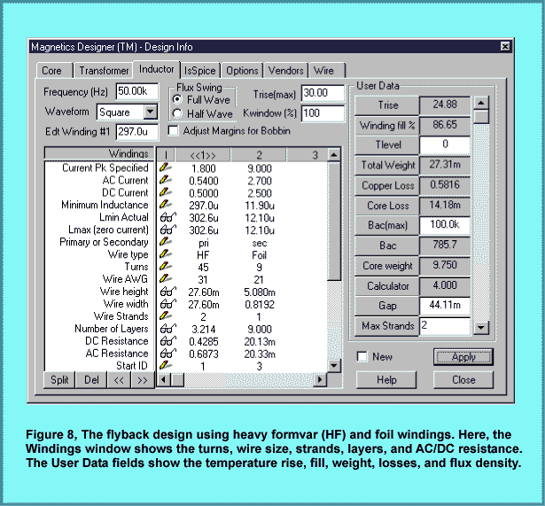
Several design changes were tried in order to improve the inductor design. It was originally assumed that Litz wire was necessary to avoid excessive losses due to potential high frequency AC resistance problems (skin and proximity effects). To test this assumption, heavy formvar (HF) wire was substituted for the Litz wire. This resulted in a significant temperature rise increase. After closely reviewing the results, it was determined that this problem was primarily due to increased AC resistance on the secondary side. Therefore, foil windings were substituted for the magnet wire on the secondary. Foil windings typically have very low AC resistance since the thickness required to achieve the desired cross-sectional area is usually much thinner than the skin depth of corresponding wire. Since a foil winding was used, the program adds layer insulation, wrappers, and end margins to prevent shorts between turns and other windings.
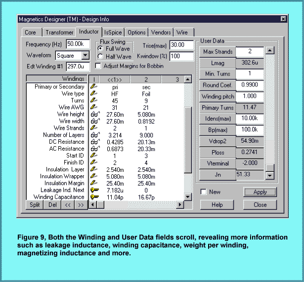
Next, the number of turns on the primary was set to 45 so that the turns ratio from primary to secondary would be exactly 5/1. To maintain the inductance at approximately .3 mh, the Gap was increased to .044 cm. The result of these changes are shown in Figure 8. The final design meeting all specifications is shown in Figures 8 and 9. It has a slightly lower peak flux, lower temperature rise, lower AC and DC resistance, and uses a smaller geometry than the initial design in Figure 7.
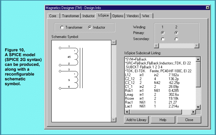
At this point, you can explore the design further by splitting windings or trying different materials. A winding sheet and design summary report can be printed out or copied to Microsoft Excel. As shown in Figure 10, Magnetics Designer can also produce a SPICE model and schematic symbol for the design. This allows you to simulate the device while it is being made. The SPICE model can be used with ANY SPICE program.
Magnetics Designer provides a simple and fast way to design custom transformers and inductors, a key part of virtually all electronic systems and many EMI filtering applications. The software even designs planar magnetics, an important part of many new high frequency applications. Magnetic design is an art that is slowly being lost as experienced designers retire. Products like Magnetics Designer help fill the void by providing intelligence and design expertise in a software tool.
From: Jeffrey P. San Jose,
CA
Dear Intusoft Tech Support:
I was tutoring a friend in basic EE and showing him how an integrator
works. Using SpiceNet,
I drew a simple op-amp circuit using a 741 as an integrator, and
was demonstrating the effect of a resistor in the feedback path
shunting the integrating capacitor. By increasing its value, I
could effectively eliminate it without deleting it. I found that
if I made the input source a combination of a simple AC (frequency
stimulus) source plus a transient PULSE source (Pulse -100m 100m
0 1m 1m...) and I was only looking at the AC response (AC Bode
plot), I would get a completely erroneous result. When I made
the input source AC only, the result was correct. In addition,
I tried the AC in combination with a Sin transient generator and
the circuit worked okay.
Why does the AC + Pulse source give bad results?
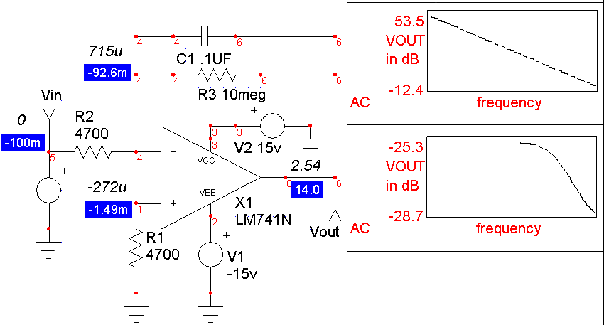
The answer is simple, but may not be obvious. When the AC + Sin source is used, the DC value of the Sin source (Sin 0 ...) is zero because the DC offset (initial value of the source) is zero. In the AC+Pulse combination, the DC value is -100m (the initial value of the pulse source) so the op-amp saturates (Figure 11). You can see this if we look at the operating point solution. In fact, this is the correct answer for the given bias condition. But that’s why the AC+Pulse simulation looks different. The AC analysis solution is affected by the biasing of the circuit. If you put an additional DC=0V value in the AC+Pulse source, then IsSpice4 will use the DC value instead of the initial pulse value for the operating bias point calculation of the circuit. The result is then the same as the AC+Sin simulation.