
 |
|
|
|
|
|
|
|
Design Validator™ is a software feature included in ICAP/4Windows, ICAP/4 Professional, and Test Designer. It provides a generalized set of capabilities including:
|
|
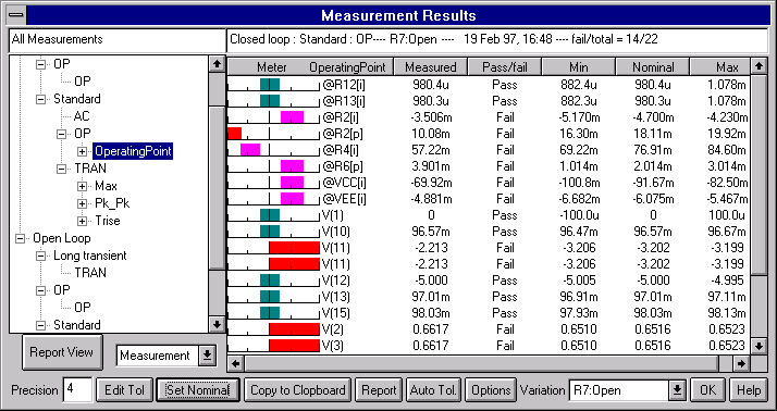
How The Design Validator Feature works: You begin by using the integrated SpiceNet schematic entry tool to capture different circuit configurations or variations. For example, one version may have a different set of values than another, or different test circuitry or different stimulus. Each circuit configuration can be assigned one or more SPICE analyses and each configuration-analysis grouping can be assigned one or more automated measurements. The combination of an analysis, a configuration, and a measurement is referred to as a “Test”. The measurements can be made on any number of nodes or devices and are setup using an easy-to-use Wizard approach. Advanced users can take advantage of IsSpice4’s powerful ICL scripting capabilities to make specialized measurements. All of the commonly required measurements are available, including cursor and event-based measurements. Measurements can be simple (i.e., max, min, pk-pk) or consist of a complex series of events (i.e., propagation delay triggered after a specific circuit condition is reached). Design Validator™ automatically simulates the multiple test configurations you have created. The results are organized into a report containing the measured (simulated) result and the pass/fail limits which are used to grade the performance as shown below. |
 |
|
Design Validator™ runs all the simulations and processes all the results WITHOUT the need for any user interaction. Evaluating design changes has never been this easy!!! The report shows which tests passed or failed based on tolerances assigned to your measurements. Different pass/fail limits can be easily assigned but defaults are inserted for you. Once setup, the Results report allows you to investigate the effects of virtually any circuit design change easily and quickly. Performed in the design phase, Design Validator allows you to set a baseline performance criteria for use in subsequent design modifications, re-designs or re-use. The design baseline can include product specification compliance, component stress results and failure propagation studies; all of which can be used for product quality management. Design Validator™ enables any part of your system to be tested and verified under any condition, including out-of-spec performance variations based on any design change or variation. With Design Validator™, test strategies can be improved and debugged by enabling virtual production studies to be undertaken without the need to build a prototype or even wait until the design process has been completed. Design Validator™ is a vast improvement over manual analysis, and dramatically reduces the time-consuming evaluation of large volumes of data. |
|
Uses and Benefits
|
|
Features
|