
 |
 |
|
STATESET, on the other
hand creates a new circuit branch in which the element output is initialized
during the entire DC operating point calculation. Once the operating point
is calculated, the input of the STATESET branch connects to its output
so the AC and Transient analyses can proceed. |
STATESET is a very
simple concept, however, standard SPICE simulators can't handle the problem.
Users of XSPICE enabled simulators can easily add a "code model"
that accomplishes the desired result. Other SPICE simulators (Pspice and
Hspice) need to add a new primitive element. |
This equation has
more than one stable solution, which can cause the SPICE DC operating
point solution to become unstable, and therefore unable to converge. This
web page describes the model with example drawings can be downloaded. |
|
A Linear PWM MODEL:
A pulse width modulator average model sets output voltage and input current
to functions of the input duty ratio. The simplest of all models results
when the switched inductor current is continuous, CCM, continuous conduction
mode. The process is governed by Z-Transform theory, requiring a zero-order
hold and a limiter to constrain the duty ratio to be between 0 and 1.
The current and voltage functions are nonlinear; but they can be made
linear for the DC solution by using a STATESET element as shown below: Normally, the duty ratio will depend on the output of a controller that senses the output current and voltage. The control law typically depends on the input and output voltage, making the overall solution nonlinear. But the STATESET element uses a constant for the duty ratio during calculation of the DC operating point; which effectively makes the system of equations linear, thus guaranteeing a unique solution. Downloads: |
Inside the Model: The following switch representation is used to make a model that relies on the superposition of the solutions for the 3 switch positions shown.
and |
The Buck Model:
The buck regulator, shown below, is used To reduce the input voltage.
The D1 switch is driven and the D2 switch is constructed using the freewheeling
diode. In CCM, D3=0. As the load current is reduced, the regulator drops
into DCM and D3 is greater than 0. |
|
Peak Current Control:
The peak inductor current can be calculated based on the measured average
value of the current, duty ratio and inductor voltage. Solving for the
duty ratio results in the Middlbrook equation, [1] above. where |
Inner
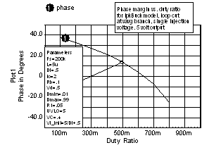
Loop: A single injection loop cut was made using GTF
theory, just after the Vavg signal. The resulting Bode plot exposes
the high duty ratio instability of peak current control. Shown below is
the phase margin vs. duty ratio resulting from the GFT analysis. |
Average
Current Control: Solving for average current as a function of duty ratio
yields: Di is the initial duty ratio and is used to remove offset, centering the output at the controlled value. That's the value used for the STATESET initial condition. The following average models that use STATESET are available from Intusoft for Buck, Boost and Buck/Boost(CCM): peak current control average current control duty ratio control |